Voltage Regulator using IC 723, Three Terminal Voltage Regulators - 7805, 7809, 7912
Prerequisite: Study of EDC course.
Experiment 8A
Study the operation of Voltage regulator using IC 723.
Objective: To study the voltage regulation characteristics and plot the response curve for line regulation and load regulation using 723 IC.
Apparatus:
- Bread board
- IC LM723 - 1No.
- Resistors(1KΩ, 2.7KΩ, 4.7KΩ, 6.8KΩ) - 1No. each
- RPS
- DRB / Potentiometer 10K - 1No.
- Capacitors 100pF - 1No.
- Connecting wires
- Ammeter 0-20 mA - 1No.
- Voltmeter 0-20V - 1No.
Circuit Diagrams:
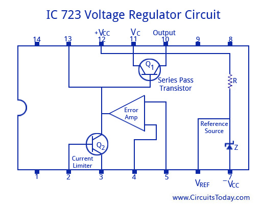
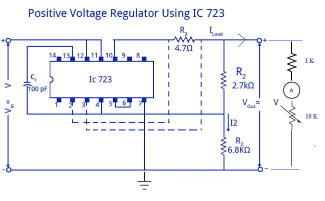
a. To get output voltage > 7V
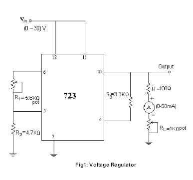
b. To get output voltage < 7V
Procedure:
I. LINE REGULATION
- Connections are made as per the circuit diagram.
- RPS is connected as Vi.
- A fixed load of 1K is kept at the output.
- Input Vi is varied from 15V to 25V in steps of 2V and Output voltage is measured.
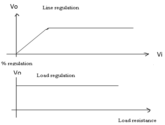
- Graph is drawn between the input voltage and output voltage.
II. LOAD REGULATION
- Connections are made as per the circuit diagram.
- RPS is connected as Vi.
- Output voltage is measured by varying the load (Potentiometer), in steps of 1mA
- Graph is drawn between the output voltage and output current (load).
Observations:
Line regulation = (ΔVout / ΔVin) / 100%
Vnl =
| Line Voltage (V) | Output Voltage (V) |
|---|---|
Load regulation
| Regulated Output (V) | Load Current(mA) | Load Resistance(KΩ) | Load Regulation |
|---|---|---|---|
% Regulation = [(Vnl - Vfl) / Vfl] * 100
Model Graph:
Result: The load regulations and line regulations are observed by the IC 723.
Outcome: After conducting this experiment students are able to use IC 723 as voltage regulator and understand its operation.
Experiment 8B
Study the operation of Three terminal fixed Voltage regulators using ICs 78xx / 79xx ( Positive and Negative Voltage Regulators)
Prerequisite: Study of EDC course.
Objective: To study the voltage regulation characteristics and plot the response curve for line regulation and load regulation using 7805, 7809, 7912 ICs.
Apparatus:
- Bread board
- ICs 7805, 7809, 7912 ICs - 1No. each
- RPS
- DRB / potentiometer 10KΩ - 1No.
- Capacitors 1000µF, 22 µF - 1No. each
- Voltmeter - 0-20V
- Connecting wires
Circuit Diagrams:

Figure.1 Fixed Positive Voltage regulator

Figure.2 Fixed Negative Voltage Regulator
Theory: A regulated power supply has to provide constant output voltage irrespective of variation in the load connected to the power supply or variation in the input unregulated power given to the power supply. This is achieved by taking the feedback from the output voltage and compared with a fixed reference voltage. Based on the error, the output voltage is adjusted.
Procedure:
For fixed positive voltage regulator (7805 and 7809):
- Connect the circuit diagram as shown in figure.1.
- Apply the unregulated voltage to the IC 7805 and note down the regulator output voltage. Vary input voltage from 7V to 20V and record the output voltages.
- Calculate the line regulation of the regulator using the formula.
- Line Regulation = ΔVO /ΔVi.
- Now, fix the input voltage as 15V and vary the load resistance RL, from 1K to 10 K ohms. Note down the regulator output voltage.
- Calculate the Load regulation of the regulator using the formula.
- Load Regulation =ΔVO / ΔIL.
- Repeat the above procedure for 7809.
For fixed negative voltage regulator (7912):
- Connect the circuit diagram as shown in figure.2.
- Apply the unregulated voltage to the IC 7912 and note down the regulator output voltage.
- Vary input voltage from 7V to 20V and record the output voltages.
- Calculate the line regulation of the regulator using the formula.
- Line Regulation = ΔVO / ΔVi.
- Now, fix the input voltage as 15V and vary the load resistance RL, from 1K to 10 K ohms. Note down the regulator output voltage.
- Calculate the Load regulation of the regulator using the formula.
- Load Regulation =ΔVO / ΔIL.
Observations:
1). For +Ve Voltage Regulator 7805
Line Regulation: (RL is constant)
| S.No. | Unregulated DC Input, Vi in Volts | Regulated DC Output, VO in Volts |
|---|---|---|
Load Regulation: (Vi is constant)
| S.No. | Load Resistance, RL in Ohms | Regulated DC output, VO in Volts |
|---|---|---|
2). For +Ve Voltage Regulator 7809
Line Regulation: (RL is constant)
| S.No. | Unregulated DC Input, Vi in Volts | Regulated DC Output, VO in Volts |
|---|---|---|
Load Regulation: (Vi is constant)
| S.No. | Load Resistance, RL in Ohms | Regulated DC output, VO in Volts |
|---|---|---|
3). For -Ve Voltage Regulator 7912
Line Regulation: (RL is constant)
| S.No. | Unregulated DC Input, Vi in Volts | Regulated DC Output, VO in Volts |
|---|---|---|
Load Regulation: (Vi is constant)
| S.No. | Load Resistance, RL in Ohms | Regulated DC output, VO in Volts |
|---|---|---|
Model Graphs(for +Ve Voltage Regulators):

Fig 3. Line Regulation
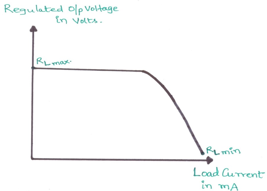
Fig 4. Load Regulation
Model Graphs(for -Ve Voltage Regulator):

Figure 5. Line Regulation for 79XX

Figure 6. Load Regulation for 79XX
Result:
Studied the 3-terminal fixed voltage regulator using IC 78XX and 79XX series &also the line regulation and load regulation of them are verified.
Outcome:
- Design of regulator and the concepts of stabilizers will be known to the students.
- Usage of IC 7805, IC 7905, and IC 723 which are fixed positive, fixed negative and variable voltage regulators respectively will be known.
VIVA Questions:
1. What is meant by line regulation?
Ans: Line regulation is expressed as percent of change in the output voltage relative to the change in the input line voltage.
2. What is meant by load regulation?
Ans: Load regulation is the capability to maintain a constant voltage (or current) level on the output channel of a power supply despite changes in the load.
3. What is the function of a series pass transistor in Linear regulated power supply?
Ans: Based on the error due to the variation in the output voltage, the transistor is driven by the control circuit to correct that error, so that the emitter of the transistor, which is the output voltage, is maintained with a steady value.
4. What is a voltage regulator?
Ans: A voltage regulator is an electronic circuit that provides a stable dc voltage independent of the load current, temperature, and ac line voltage variations.
5. What are the advantages of IC voltage regulators?
Ans: Low cost, high reliability, reduction in size, excellent performance.
6. What is meant by current limiting?
Ans: Current limiting refers to the ability of a regulator to prevent the load current from increasing above a max value, in order to protect the power supply.
7. Give the drawbacks of linear regulators.
Ans: Efficiency is low.
8. What is thermal shut down?
Ans: When the temperature on the IC increases beyond a high limit (safe value of operation), the output of the power supply will be switched OFF.
9. What are the limitations of 3 pin fixed voltage regulators?
Ans: There is no short circuit protection. Output voltage can not be varied.
10. How current boosting is achieved in 723 IC?
Ans: By adding another npn transistor in Darlington mode with the series transistor.
-
UpdatedOct 22, 2016
-
Views28,865