HDL code-Design of 8-to-3 Encoder (Without Priority)
Prerequisites: Study the functionality of Encoder.
Learning Objective: To Design and verify the functionality of 8 to 3 Encoder.
Software and Hardware: Xilinx ISE 9.2i and FPGA Spartan-3E.
Theory:
An Encoder is a device, circuit, transducer, software program, algorithm or person that converts information from one format or code to another. The purpose of encoder is standardization, speed, secrecy, security, or saving space by shrinking size. Encoders are combinational logic circuits and they are exactly opposite of decoders. They accept one or more inputs and generate a multibit output code.
Encoders perform exactly reverse operation than Decoder. An Encoder has M input and N output lines. Out of M input lines only one is activated at a time and produces equivalent code on output N lines. If a device output code has fewer bits than the input code has, the device is usually called an encoder.
Octal to binary encoder
Octal-to-Binary take 8 inputs and provides 3 outputs, thus doing the opposite of what the 3-to-8 decoder does. At any one time, only one input line has a value of 1. The figure below shows the truth table of an Octal-to-binary encoder.
| Inputs | Outputs | |||||||||
|---|---|---|---|---|---|---|---|---|---|---|
| D0 | D1 | D2 | D3 | D4 | D5 | D6 | D7 | E2 | E1 | E0 |
| 1 | 0 | 0 | 0 | 0 | 0 | 0 | 0 | 0 | 0 | 0 |
| 0 | 1 | 0 | 0 | 0 | 0 | 0 | 0 | 0 | 0 | 1 |
| 0 | 0 | 1 | 0 | 0 | 0 | 0 | 0 | 0 | 1 | 0 |
| 0 | 0 | 0 | 1 | 0 | 0 | 0 | 0 | 0 | 1 | 1 |
| 0 | 0 | 0 | 0 | 1 | 0 | 0 | 0 | 1 | 0 | 0 |
| 0 | 0 | 0 | 0 | 0 | 1 | 0 | 0 | 1 | 0 | 1 |
| 0 | 0 | 0 | 0 | 0 | 0 | 1 | 0 | 1 | 1 | 0 |
| 0 | 0 | 0 | 0 | 0 | 0 | 0 | 1 | 1 | 1 | 1 |
Table: Truth Table of octal to binary encoder
For an 8-to-3 binary encoder with inputs I0-I7 the logic expressions of the outputs Y0-Y2 are:
E0 = I1 + I3 + I5 + I7
E1= I2 + I3 + I6 + I7
E2 = I4 + I5 + I6 +I7
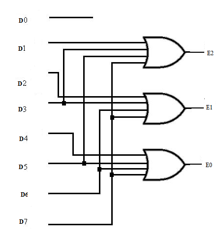
Fig. Logic Diagram of octal to binary encoder
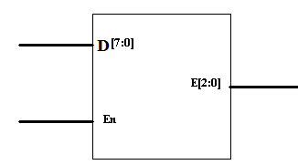
Block Diagram:
Verilog Code:
module encoder8_3(Eo, Din, En);
    input [7:0] Din;
    input En;
    output [2:0]Eo;

    reg [2:0]Eo;

    always @ ( En or Din)
    begin
        if (En)
        begin
            case (Din)
            8'o0: Eo = 3'b000;
            8'o1: Eo = 3'b001;
            8'o2: Eo = 3'b010;
            8'o3: Eo = 3'b011;
            8'o4: Eo = 3'b100;
            8'o5: Eo = 3'b101;
            8'o6: Eo = 3'b110;
            8'o7: Eo = 3'b111;
            default: $display("Error!");
            endcase
        end
    end
endmodule
Test Bench Code:
module encountrtest_v;

    // Inputs
    reg [7:0] a;
    reg en;

    // Outputs
    wire [2:0] o;

    // Instantiate the Unit Under Test (UUT)
    encoder uut(
        .o(o),
        .a(a),
        .en(en)
    );

    initial begin
        a = 8'b00000000;
        en = 1'b1;
        #10 a = 8'b00000001;
        #10 a = 8'b00000010;
        #10 a = 8'b00000100;
        #10 a = 8'b00001000;
        #10 a = 8'b00010000;
        #10 a = 8'b00100000;
        #10 a = 8'b01000000;
        #10 a = 8'b10000000;
    end

endmodule
Simulation Results:
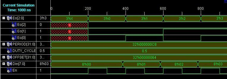
Result: Designed and verified 8 to 3 encoder is by synthesizing and simulating the VERILOG code.
Learning Outcome:
8X3 Encoder has been simulated and also their output waveforms have been observed.
Viva questions:
- How many 4X2 Encoders are needed to construct 16x4 Encoder?
- What is the difference between Decoder and Encoder?
- What are the applications of Encoder?
- What is the difference between Encoder and Multiplexer?
- What is importance of enable line in Encoder?
-
UpdatedOct 30, 2016
-
Views31,628