Integrator and Differentiator using IC 741 Op-Amp
Prerequisite: Know the theory about the experiment. Study the pin diagram and functioning of each pin of IC 741. Study how an integrator and a differentiator work.
Objective: To study the working of op-amp as differentiator and integrator.
Apparatus:
| Bread board | 1 |
| Regulated power supply | 1 |
| CRO | 1 |
| IC 741 | 1 |
Resistors 10k , 100K , 100K |
1 each |
| Resistors 1.5 k, 150 |
1 each |
Capacitor 0.01 F, 0.1F F, 0.1F |
1 each |
| Function generator 1 Hz to 2MHz | 1 |
| Connecting wires |
Circuit diagrams:
Practical Integrator Rf = 100k, R1 = 10K, Cf = 0.1f
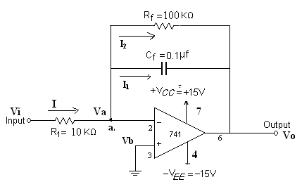
Fig 1. Integrator Circuit
Practical Differentiator Rf = 1.5 k, R1 = 150, Cf = 0.1f, C1 = 0.01f
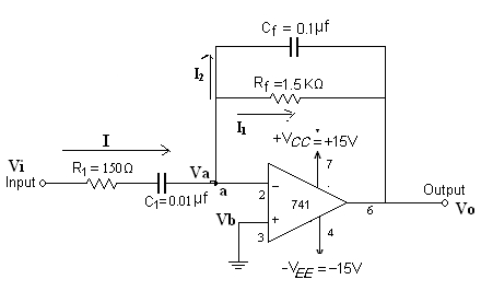
Fig 2. Differentiator circuit
Procedure:
INTEGRATOR:
- Connect the circuit as shown in fig 1.
- Apply a symmetrical square wave of 2Vp-p amplitude and 1 KHz frequency.
- Connect the input and output of the circuit to channel 1 and channel 2 of the CRO respectively and observe the waveforms.
- Draw the waveforms along with the levels on a graph.
- Compare the practical values with theoretical values.
- Repeat the same for sine-wave.
DIFFERENTIATOR:
- Connect the circuit as shown in fig 2.
- Apply a symmetrical triangular wave of 2Vp-p amplitude and 1KHz frequency.
- Connect the input and output of the circuit to channel 1and channel 2 of the CRO respectively and observe the waveforms.
- Draw the waveforms along with the levels on a graph.
- Compare the practical values with theoretical values.
- Repeat the same for the sine-wave.
TABULAR FORM:
INTEGRATOR:
| S.No | Input Waveform | Time period | Amplitude | Output waveform | Amplitude | Time period |
|---|---|---|---|---|---|---|
| 1 | Square wave (1KHz) | 1ms | 2Vp-p | |||
| 2 | Sine wave (1KHz) | 1ms | 2Vp-p |
DIFFERENTIATOR:
| S.No | Input Waveform | Time period | Amplitude | Output waveform | Amplitude | Time period |
|---|---|---|---|---|---|---|
| 1 | Triangular wave (1KHz) | 1ms | 2Vp-p | |||
| 2 | Sine wave (1KHz) | 1ms | 2Vp-p |
Expected Waveforms:
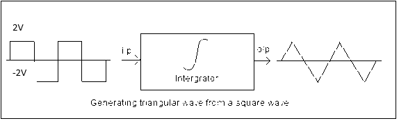
a. Integrating square wave
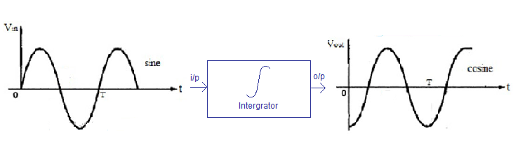
b. Integrating sine wave waveform
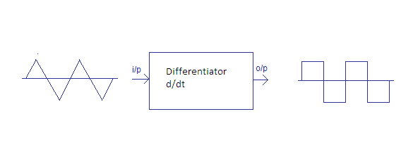
c. Differentiator output for square wave
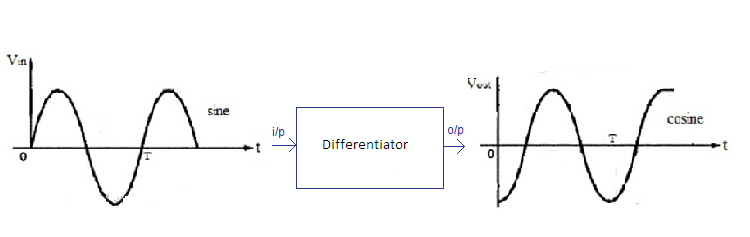
d. Differentiator output for sine wave waveform
Result: Designed and verified differentiator and integrator circuits using Op-Amp 741.
Outcome: After conducting this experiment students are able to design the circuits using op-amps to perform integration and differentiation operations for different waveforms.
Viva Questions:
1. Define integrator.
Ans: An integrator is a device to perform the mathematical operation known as integration, a fundamental operation in calculus. The integration function is often part of engineering and scientific calculations. Electronic analog integrators were the basis of analog computers.
2. Define differentiator.
Ans: A Differentiator is a circuit that is designed such that the output of the circuit is proportional to the time derivative of the input.
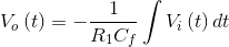
3. Write down output voltage formula for the integrator.
Ans:
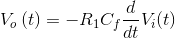
4. Write down output voltage formula for the differentiator.
Ans:
5. What is the output of the differentiator for square wave input?
Ans: Spikes
6. What are the problems in an ordinary op-amp differentiator? What are the changes in the circuit of the practical differentiator to eliminate these problems?
Ans: Problems in an Ordinary op-amp differentiator are instability and high frequency noise. A Resistor is added in series with the capacitor at the input and a capacitor is added in parallel to the resistor in the feedback circuit in the practical differentiator to eliminate the above problems.
7. What are the problems in an ordinary op-amp Integrator? What are the changes in the circuit of a practical integrator?
Ans: The gain of an integrator at low frequency is very high and the circuit goes to saturation. The feedback capacitor is shunted with a resistor in the practical integrator to overcome the above problem.
8. What is a lossy integrator?
Ans: The practical integrator is known as lossy integrator.
9. How a sine wave and cosine wave can be discriminated?
Ans: When t = 0, Sine wave amplitude is zero and the cosine wave amplitude is maximum.
10. Why integrators are preferred over differentiators in electronic circuits?
Ans: In differentiators, the gain increases at high frequency and are not stable.
-
UpdatedOct 14, 2016
-
Views93,316