IC 555 Timer - Monostable and Astable Multivibrator Circuits
Prerequisite: Study the operation of Monostable and Astable Multivibrator.
Objective:
- To design a monostable multivibrator for a required pulse width using 555 timer.
- To design astable multivibrator for a given frequency using 555 timer.
Apparatus:
| Bread board | 1 |
| CRO (20MHz) | 1 |
| IC 555 | 1 |
| Resistors | |
47K |
2 |
| 2.2K |
1 |
| 10K |
1 |
| 100K |
1 |
| Capacitors | |
| 0.01μF | 2 |
| 0.1μF | 2 |
| PN Diode 1N4007 | 1 |
| RPS | 1 |
| Function generator (10 Hz-20MHz) | 1 |
Design:
Monostable Multivibrator:
T = 1.1R1C1
Let C1 = 0.01µF & R1 = 47K then T = 0.3ms(approx)
Astable Multivibrator:
For 55% duty cycle choose RB = 10K
THIGH = Tc = 0.693 (RA + RB)C
TLOW = Td = 0.693 RBC
T = THIGH + TLOW = 0.693 (RA + 2RB)C
f = 1/T = 1.44/ (RA + 2RB)C
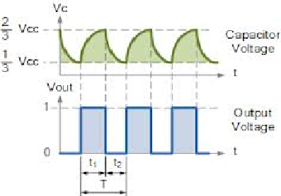
% duty cycle, D = Tc / T * 100 = (RA + RB) / (RA + 2RB) * 100
Circuit diagrams:
Monostable Multivibrator:
Triggering Circuit
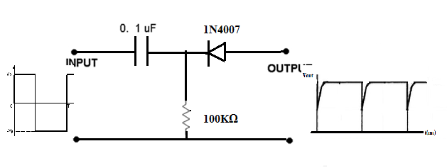
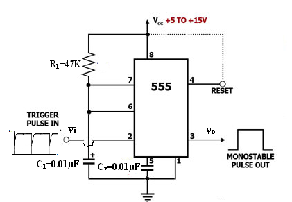
Fig 1. Monostable Multivibrator
Astable Multivibrator:
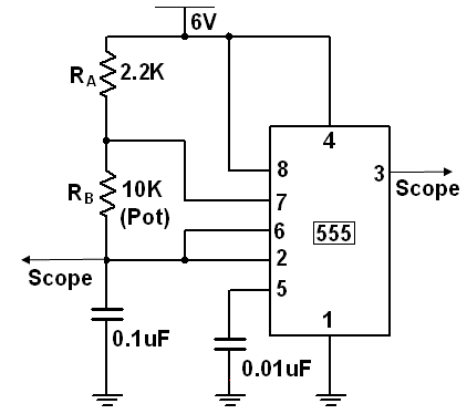
Fig 2. Astable Multivibrator
Procedure:
Monostable Multivibrator:
- Connect the circuit as shown in the circuit diagram Fig 1.
- Apply Negative triggering pulses of frequency 1 KHz at pin 2.
- Observe the output waveform at pin 3 and measure capacitor voltage across it at pin 6.
- Theoretically calculate the pulse duration as T = 1.1R1C1
- Compare it with experimental values.
- Plot the graph for the input and output waveforms.
Astable Multivibrator:
- Connect the circuit as shown in the circuit diagram Fig 2.
- Observe the output waveform at pin 3 and measure capacitor voltage across it at pin 6.
- Theoretically calculate the Time period as T = 0.69 RBC + 0.69 (RA + RB)C.
- Compare it with experimental values.
- Plot the graph for the input and output waveforms.
Model Wave Forms:
Monostable Multivibrator:
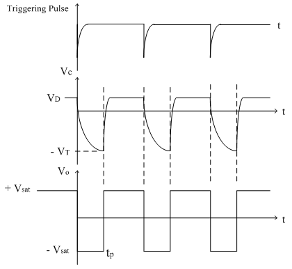
Waveforms at Capacitor and monostable output
Astable Multivibrator:
Result: Designed and verified the waveforms of monostable multivibrator and Astable multivibrator using 555 Timer.
Outcome: After conducting this experiment, students are able to design the monostable multivibrator and Astable multivibrator using IC 555 Timer.
VIVA Questions:
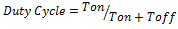
1. Define duty cycle?
Ans: The ratio of the time of the high output to the time of the total output is the duty cycle
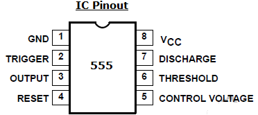
2. Draw the pin diagram of 555 timers?
Ans:
3. What are the applications of 555 timers in monostable mode?
Ans: Missing pulse detector, Frequency divider, Pulse width modulation etc.
4. Explain capacitor output waveform in monostable mode?
Ans: Tin stable state, FF output is zero and the discharge transistor Qd is ON and the capacitor voltage is zero through Qd. Whenever a trigger is given, FF goes to high level, Qd is OFF and the Capacitor charges through R till it reaches 2/3 Vcc which makes the FF output to zero and the process repeats. The charging time of the capacitor from zero to 2/3 Vcc is the time of the pulse width.
5. Write down the expression for output pulse width in monostable mode?
Ans: T = 1.1R1C1
6. Why the number has come for 555 IC as 555?
Ans: It has three 5K Resistors at the input of the comparators to get 2/3 Vcc and 1/3 Vcc, hence the name came as 555.
7. Write down the expression for output pulse width in Astable mode?
Ans: T = 0.69(RA + 2RB)C , TON = 0.69(RA + RB)C, TOFF = 0.69RBC
8. What are the applications of 555 timers in Astable mode?
Ans: Square wave generator, FSK generator, pulse position modulator etc.
9. What is a quasi stable state and what is a steady state?
Ans: A quasi stable state is also known as temporary state, where the output stays in this state only for a fixed time and goes back to the stable state after that time period. A stable state is a state where the output will be in that state until unless an external trigger is given.
10. What are the other names for the Monostable Multivibrator and Astable Multivibrator?
Ans:
Monostable Multivibrator: pulse width generator, one shot, delay generator.
Astable Multivibrator: free running oscillator, clock signal, square wave generator.
-
UpdatedOct 22, 2016
-
Views31,897