Waveform Generator using Op Amp 741
Prerequisite: Study the EDC and PDC courses.
Objective: To generate sine, triangular and square waveforms and to determine the Frequency of oscillations.
Apparatus:
- Op-Amp IC 741 - 2No.
- Bread board
- Capacitor 0.1µF - 3No.
- RPS (0 - 30V) - 1No.
- Resistors - 10K
 - 2No., 470K - 1No.,1K - 3No.
 - Connecting wires
- CRO(20MHz)
Circuit diagrams:
Sine Wave Generator: (RC phase shift oscillator)
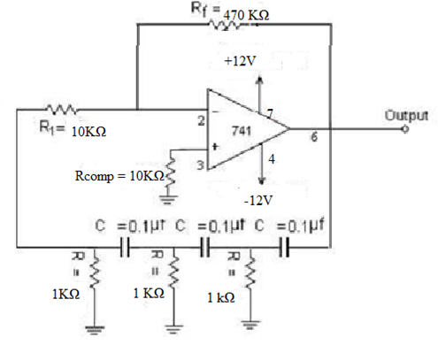
Fig - 1
Square and Triangular Wave Generator:
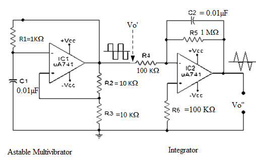
Fig - 2
Theory:
RC oscillator is build using an amplifier and a RC network in feedback. For any oscillator the two prime requirements to generate sustained and constant oscillations are
- The total phase shift around loop must be 00 or 3600 degrees.
- The loop gain should be equal to unity.
This is known as “Barkhausen Criterion”
In RC phase shift oscillator op-amp is used as an amplifier in inverting configuration. It gives 180o phase shift in its output. So the RC feedback network following the amplifier has to produce additional 180o phase shift to make total phase shift 360o / 0o.
The circuit oscillates at a frequency F = 1 / 2πRC√6
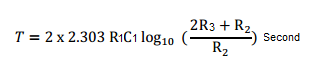
The time period of the output of the uA741 square wave generator can be expressed using the following equation:

The common practice is to make the R3 equal to R2. Then the equation for the time period can be simplified as: T = 2.1976R1C1
The frequency can be determined by the equation: F = 1/T
Procedure:
For Sine Wave Generation:
- Connect the circuit as per the circuit diagram shown in Fig 1.
- Give +12V, -12V and ground to circuit from power supply
- Observe the output on the CRO.
- Calculate theoretical and practical output signal frequency and compare them.
For Square and Triangular Wave Generation:
- Connect the circuit as per the circuit diagram shown in Fig 2.
- Observe square wave at Vo’ and Triangular wave at Vo” as shown in figure 3.
- Plot the waveforms on the graph sheet.
- Calculate the frequency theoretically and compare them with the practical one.
Expected Waveforms:
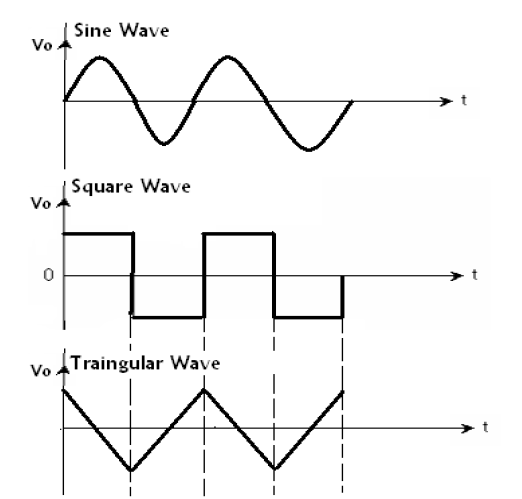
Fig - 3.
Result:
Designed and verified the waveforms of waveform Generator using IC741.
Outcome:
After conducting this experiment, students are able to design and generate sine, square and triangular waveforms using IC741.
Viva Questions:
1. What are the different ways of generating Sinusoidal waves?
Ans: Sinusoidal voltage wave forms are generated using Oscillators. The different types of oscillators for generating sine wave are: Phase shift oscillator, Wein-Bridge oscillator, Hartley oscillator, Colpitts Oscillator etc.
2. What are different ways of generating square wave voltage waveforms?
Ans: Astable multivibrator using 741 or 555 ICs, zero crossing comparators by giving sinusoidal wave, Schmitt trigger, PLL circuit etc.
3. What is phase-shift oscillator?
Ans: A phase-shift oscillator contains an inverting amplifier (creating 180 deg phase shift) and a feedback circuit which shifts the phase of the amplifier output by 180 degrees. The total phase shift will be 00 or 3600 degrees to meet the Barkhausen criterion.
4. What is formula for frequency of oscillations for RC phase shift oscillator?
Ans: f = 1 / 2πRC√6
5. How a triangular wave can be generated?
Ans: Integrating square wave.
6. What is formula for frequency of oscillations for Astable square wave generator?
Ans:
f = 1/T
7. What is the frequency of oscillations of triangular wave when it is generated by integrating the square wave?
Ans: Same as the frequency of the input square wave.
8. For a circuit to act as an integrator, how the time constant has to be?
Ans: It has to be of high value.
9. What is barkhausen criterion for oscillations?
Ans: The total phase shift around loop must be 00 or 3600 degrees.
The loop gain should be equal to unity. i.e. |Aβ| = 1
10. Why three RC sections are used in the feedback for RC phase shift oscillator?
Ans: It is difficult to generate 1800 deg phase shift with two RC sections. More than 3 sections can also be used, but it complicates the circuit diagram (more components are required).
-
UpdatedOct 22, 2016
-
Views56,545