Design of 2-to-4 decoder
Prerequisites: Study of the functionality of Decoder.
Objective: To design 2 to 4 line decoder using Verilog HDL, obtain the simulation and synthesis.
Software and Hardware: Xilinx ISE 9.2i and FPGA Spartan-3E.
Theory:
Decoders are circuits with two or more inputs and 2n outputs. Based on the input code, only one of the output is selected.
The truth table of 2-to-4 line decoder is
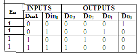
Developed into a circuit it looks like
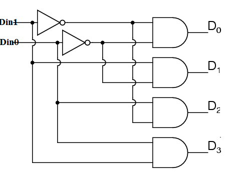
Figure: Gate Level Representation of 2 to 4 Line Decoder (Logic Diagram)
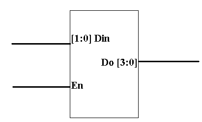
Block Diagram:
Verilog Code:
(a). Using else if construct:
module decoder(Do, Din, En);
    input [1:0] Din;
    input En;
    output [3:0] Do;

    reg [3:0] Do;

    always @(En or Din)
    begin
        if (En)
        begin
            if (Din == 2'b00)
                Do= 4'b0001;
            else if (Din == 2'b01)
                Do = 4'b0010;
            else if (Din == 2'b10)
                Do = 4'b0100;
            else if (Din == 2'b11)
                Do = 4'b1000;
            else
                $display("Error!");
        end
    end
endmodule
Test Bench Code:
module decoder_tb_v;
    reg [1:0] Din;
    reg En;
    wire [3:0] Do;

    decoder24 uut(
        .Do(Do),
        .Din(Din),
        .En(En)
    );
    initial begin
        // Initialize Inputs
        En = 1;
        Din =2'b00; #20;
        Din = 2'b01; #20;
          Din = 2'b10; #20;
        Din = 2'b11; #20;
    end
endmodule
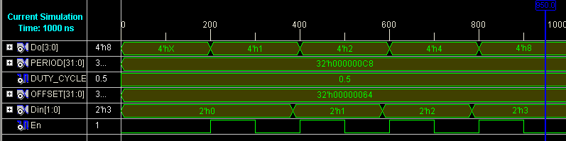
Simulation Results:

(b). Using case construct:
module decoder_case(Do, Din, En);
    input En;
    input [1:0] Din;
    output [3:0]Do;

    reg [3:0]Do;

    always @ (En or Din)
    begin
        if (En)
        begin
            case (Din)
                2'b00: Do = 4'b0001;
                2'b01: Do = 4'b0010;
                2'b10: Do = 4'b0100;
                2'b11: Do = 4'b1000;
                default: $display("Error!");
            endcase
        end
    end
endmodule
Simulation Results:
Result: Designed 2x4 decoder and verified by synthesizing and simulating the VERILOG code.
Learning Outcome: After completion of this experiment, students are able to design Decoder circuit using Verilog VHDL.
Viva Questions:
- How many 2X4 Decoders are needed to construct 4X16 Decoder?
- What is the difference between Decoder and Encoder?
- What are the applications of Decoder?
- What is the difference between Decoder and Demultiplexer?
- What is importance of enable line in Decoder?
- For n- 2n decoder, how many input lines and how many output lines exist?
-
UpdatedOct 30, 2016
-
Views33,725