Op-Amp Applications – Adder, Subtractor & Comparator
Prerequisite: Know the theory about the experiment. Study the pin diagram and functioning of each pin of IC 741.
Objective: To study the working of op- amp as adder, subtractor and comparator.
Apparatus:
| Regulated power supply (0-30V dual) | 1 |
| CRO (20 MHz) | 1 |
| IC 741 | 1 |
| Resistors | |
1K |
2 |
| 10K |
4 |
| 3.3K |
1 |
| 2.2K |
1 |
| IC Trainer Kit | 1 |
| Voltmeter 0 to 20V | 1 |
| Function generator 1 Hz to 2 MHz | 1 |
| Connecting wires |
Circuit diagrams:
ADDER: Rf = 10k R1 = R2 = 10k R = 3.3k
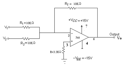
Fig 1. OP-AMP ADDER
If R1 = R2 = Rf = R, then
V0 = - (V1 + V2)
SUBTRACTOR: Rf & R = 10k, R1 & R2 = 10k
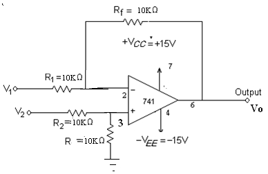
Fig 2. OP-AMP SUBTRACTOR
If Rf = R1 = R2 = R, then V0 = V2 - V1
COMPARATOR: R, R = 1k (2 Nos.), R0 = 2.2k
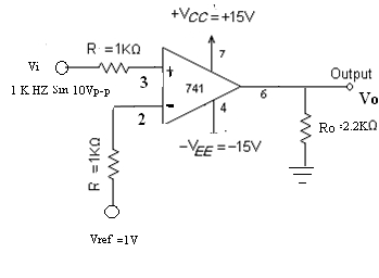
Fig 3. COMPARATOR
Vo = +Vsat for Vi > Vref
= -Vsat for Vi < Vref
Procedure:
ADDER:
- Connect the circuit as shown in the adder circuit diagram (fig 1).
- Apply the supply voltages of +15V to pin 7 and -15V to pin 4 of IC 741 respectively from IC Trainer kit. Connect the ground to the ground point.
- Apply DC voltage from regulated power supply to inputs V1 and V2.
- Apply V1 = 1 V and Increase V2 from 0V to 5V in steps of 1V. Repeat the same for V1 = 3V and V1 = 5V.
- Note down the Vo using Voltmeter.
- Compare theoretical and practical values.
SUBTRACTOR:
- Connect the circuit as shown in the subtractor circuit diagram (fig 2).
- Apply the supply voltages of +15V to pin 7 and -15V to pin 4 of IC 741 respectively from IC Trainer kit. Connect the ground to the ground point.
- Apply DC voltage from regulated power supply to inputs V1 and V2.
- Apply V1 = 1V and Increase V2 from 0V to 5V in steps of 1V. Repeat the same for V1 = 3V and V1 = 5V.
- Note down the Vo using Voltmeter.
- Compare theoretical and practical values.
COMPARATOR:
- Connect the circuit as shown in the figure 3.
- Apply the supply voltages of +15V to pin 7 and -15V to pin 4 of IC 741 respectively from IC Trainer kit. Connect the ground to the ground point.
- Set the reference voltage as 1V DC.
- Apply sine wave of 10Vp-p with1KHz frequency from the function generator as Vi.
- Check the output in CRO and calculate the amplitude of the output wave form.
- Plot the waveforms on graph sheets as shown in fig 4.
- Compare the output wave form amplitude with input signal amplitude.
- Change the reference voltage as -1V and repeat the experiment.
TABULAR FORMAT
ADDER:
| S.No | D.C Voltage at input V1 (V) | D.C Voltage at input V2 (V) | D.C Voltage at Output Vo (V) |
|---|---|---|---|
| 1 | |||
| 2 | |||
| 3 | |||
| 4 |
SUBTRACTOR:
| S.No | D.C Voltage at input V1 (V) | D.C Voltage at input V2 (V) | D.C Voltage at Output Vo (V) |
|---|---|---|---|
| 1 | |||
| 2 | |||
| 3 | |||
| 4 |
COMPARATOR:
| S.No | D.C Reference Voltage at input Vref (V) | A.C Peak Voltage at input Vi (V) | Voltage at Output Vo (V) | Duty cycle for Vo | Theoretical Voltage Vo (V) |
|---|---|---|---|---|---|
| 1 | |||||
| 2 | |||||
| 3 | |||||
| 4 |
Expected waveforms:
COMPARATOR:
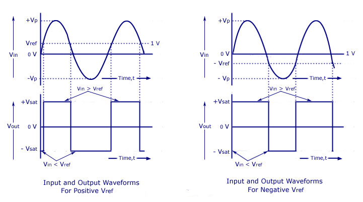
Fig 4.
Result: Verified the functioning of adder, subtractor and comparator circuits using Op-Amp 741.
Outcome: After conducting this experiment, students are able to design the circuits using op-amps to perform addition, subtraction and comparison operations.
Viva Questions:
1. Mention some of the linear applications of op–amps?
Ans: Adder, subtractor, voltage –to- current converter, current –to- voltage converters, instrumentation amplifier, filter etc.
2. Mention some of the non – linear applications of op-amps?
Ans: Rectifier, peak detector, clipper, clamper, sample and hold circuit, log amplifier, anti –log amplifier, multiplier etc.
3. What happens when the common terminal of V+ and V- sources is not grounded?
Ans: If the common point of the two supplies is not grounded, twice the supply voltage will get applied and it may damage the op-amp.
4. What are the ideal characteristics of an op-amp?
Ans: Ideal characteristics of an op-amp are
- Open loop gain infinite
- Input impedance : infinite
- Output impedance : zero
- Bandwidth : infinite
5. What is a comparator?
Ans: A comparator is a circuit which compares a signal voltage applied at one input of an op-amp with a known reference voltage at the other input. It is an open loop op-amp with output + /- Vsat.
6. Why IC 741 is not used for high frequency applications?
Ans: IC741 has limited bandwidth because of the predominance of capacitance present in the circuit. As frequency increases, the output gets reduced.
7. In the comparator circuit, if the reference voltage is zero, what is the duty cycle of the Vo. How the duty cycle is effected by varying the reference voltage (in the positive direction and –ve direction).
Ans: 50%, Duty cycle decreases if the reference voltage is increased and it is increased when reference voltage is reduced.
8. A comparator converts sinusoidal wave to __ wave.
Ans: Square wave.
9. What is duty cycle?
Ans: It is the ratio of the time period of the positive cycle to that of the time period of the entire cycle in percentage.
10. What is slew rate? What are its units?
Ans: It is the rate of change of the output voltage when a step input voltage is given. It is measured as V/ Sec.
Sec.
-
UpdatedOct 14, 2016
-
Views57,029