Sequence Detector
Prerequisites: Study the functionality of Sequence Detector
Learning Objective: To develop the source code for sequence detector (sequence 1101) by using VERILOG and obtain the simulation and synthesis.
Software and Hardware: Xilinx ISE 9.2i and FPGA Spartan-3E.
Theory:
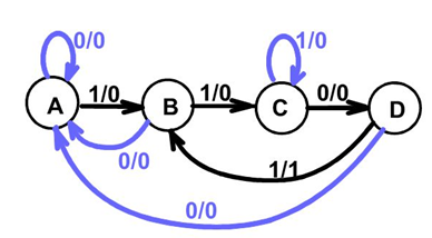
A sequence detector accepts as input of a string of bits: either 0 or 1. Its output goes to 1 when a target sequence has been detected. There are two basic types: overlap and non-overlap. In a sequence detector that allows overlap, the final bits of one sequence can be the start of another sequence. The present example is 1101 sequence detector. It raises an output of 1 when the latest binary bits received are 1101.
Verilog Code:
/* This design models a sequence detector using Mealy FSM.
   Whenever the sequence 1101 occurs, output goes high. */

module firstFSM (
 input wire clk,
 input wire rst,
 input wire sequence,
 output reg tick
);

// State declarations
localparam a = 2'b00;
localparam b = 2'b01;
localparam c = 2'b10;
localparam d = 2'b11;

// Signals
reg presentState;
reg nextState;

// State assignments
always @ (posedge clk, posedge rst)
begin
if(rst) presentState <= a;
else if(clk) presentState <= nextState;
end

// Next state logic

always @ *
begin
// Default or unassigned states remain same
nextState = presentState;
tick = 1'b0;

case(presentState)
    a : if(sequence) nextState = b;
    b :
        begin
         if(sequence) nextState = c;
         else nextState = a;
        end
    c : if(~sequence) nextState = d;
    d :
        begin
        if(sequence)
            begin
             tick = 1'b1;
             nextState = b;
            end
        else nextState = a;
        end
    default :
            begin
             tick = 1'b0;
             nextState = a;
            end
endcase
end
endmodule
TEST BENCH
`timescale 1 ns / 1 ns
module firstFSMTest;

// Signals
reg clk, rst;
reg sequence;
wire tick;

// Initialise reg ports
initial
begin
 clk = 1'b0;
 sequence = 1'b0;
end

// Set initial reset
initial
begin
 rst = 1'b1;
 #30 rst = 1'b0;
end

// Set occurance of sequence
initial
begin
 #30 sequence = 1'b1;
 #20 sequence = 1'b0;
 #20 sequence = 1'b0;
 #20 sequence = 1'b1;
 #20 sequence = 1'b1;
 #20 sequence = 1'b0;
 #20 sequence = 1'b1;
 #20 sequence = 1'b0;
 #20 sequence = 1'b1;
end

// Initialise uut
firstFSM uut (.clk(clk),
    .rst(rst),
    .sequence(sequence),
    .tick(tick)
);
always #10 clk = ~clk;

endmodule
Simulation results:

Result: Thus the program for sequence detector has been verified and also simulation and synthesis reports have been verified.
Learning outcome: After completion of this experiment, students are able to design sequence detector using Verilog code.
-
UpdatedOct 15, 2016
-
Views6,502