Schmitt Trigger Circuits - using IC 741
Prerequisite: Study of PDC course.
Objective: To Design a Schmitt trigger circuit using IC 741 and verify the output wave forms.
Apparatus:
| Bread board | 1 No. |
| Regulated power supply | 1 No. |
| Function generator | 1 No. |
| CRO | 1 No. |
| IC 741 | 1 No. |
| Resistors | |
100K |
2 No.s |
| R1 | 2 No.s |
| 1K |
1 No. |
| 10K |
1 No. |
| 5.1K |
1 No. |
| Capacitor | |
| 0.01μF | 2 No.s |
Design: To design a Schmitt trigger for a given value of +Vsat, -Vsat, UTP and LTP.
+Vsat = Vcc - 3V (approx)
-Vsat = Vee + 3V (approx)
Select Vcc and Vee as per the design requirements.
UTP and LTP depends on β i.e. R2 / (R1 + R2). Select the resistors as per the UTP and LTP requirements.
Design a Schmitt Trigger for +Vsat = 9V and -Vsat = - 6V and UTP and LTP as 3V and -2V. For this requirement, Vcc = +12V and Vee = - 9V and the β = 1/3 ( R1 can be selected as 1K which gives R2 as 2K)
Circuit diagrams:
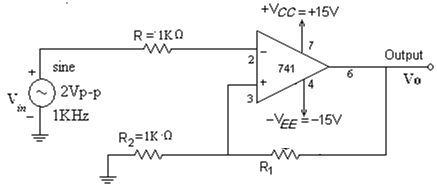
Fig 1. Schmitt trigger using IC 741
Procedure:
Using IC 741:
- Connect the circuit as shown in fig 1(a) as Schmitt trigger using IC 741.
- Give a 5 Vp-p sine wave of 1 kHz as input.
- Observe the wave form on CRO and measure UTP and LTP, Vsat and - Vsat.
- Use X-Y mode in CRO and observe hysteresis curve.
- Repeat the above experiment for R1 = 5.1Kohms and 15 Kohms and observe the effect.
Expected waveforms:
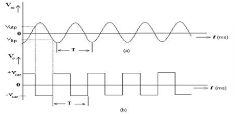
(a) Input wave form (b) output wave form
Observations:
| Parameter | Input | Output |
|---|---|---|
| Voltage(Vp-p), V | ||
| Time period - Positive Half cycle(ms) | ||
| Time period - Negative Half cycle(ms) | ||
| Theoretical | Observed | |
| UTP | ||
| LTP | ||
Result: Designed and verified Schmitt trigger circuit using IC 741.
Outcome: After conducting this experiment students are able to design the Schmitt trigger using IC 741 op amp.
VIVA Questions:
1. What are the circuits used to generate square wave?
Ans: Schmitt Trigger, Astable Multivibrator, Zero Cross Detector, PLL.
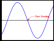
2. Short notes on zero crossing detector?
Ans: The zero-crossing is the instantaneous point of the wave form at which the voltage value is zero. In a sine wave or other simple waveform, this normally occurs twice during each cycle. Zero cross detector detects this point.
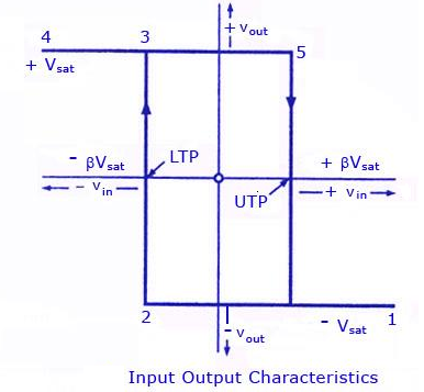
3. Define hysteresis width?
Ans: When the input is higher than a certain chosen threshold, the output is high; when the input is below a different (lower) chosen threshold, the output is low; when the input is between the two, the output retains its value. This dual threshold action is called hysteresis.
4. What are the other names for Schmitt Trigger?
Ans: Regenerative Comparator, Squarer Unit.
5. What is the duty cycle of the output square wave of the Schmitt Trigger?
Ans: 50%
6. What is a Schmitt Trigger?
Ans: Schmitt trigger is a regenerative comparator. It converts sinusoidal input into a square wave output. The output of Schmitt trigger swings at upper and lower threshold voltages, which are the reference voltages of the input waveform.
7. For what requirements, Schmitt Trigger is used?
Ans: When two levels are to be compared there may be oscillation at the border. Having hysteresis this problem is solved.
8. Define UTP and LTP. What are the values of UTP and LTP for the above circuit?
Ans: Upper threshold(Trigger) point, Lower Threshold (Trigger) points – these are the points where the input signal is compared. The values are UTP = +Vsat . R2 / (R1 + R2) and LTP = -Vsat . R2 / (R1 + R2)
9. What is the basic difference between the comparator and Schmitt trigger?
Ans: comparator compares with a fixed reference where as Schmitt trigger compares at two different references UTP and LTP.
10. Which type of feedback is used in Schmitt trigger?
Ans: +ve feedback
-
UpdatedOct 22, 2016
-
Views22,859