Johnson / Ring counter
Prerequisites: Study of the functionality of Johnson/Ring counter.
Learning Objective: To develop the source code for Johnson/Ring counter by using VERILOG and obtain the simulation and synthesis.
Software and Hardware: Xilinx ISE 9.2i and FPGA Spartan-3E.
Theory:
JOHNSON COUNTERS:
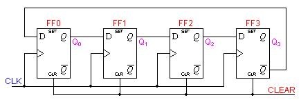
Johnson counters are a variation of standard ring counters, with the inverted output of the last stage fed back to the input of the first stage. They are also known as twisted ring counters. An n-stage Johnson counter yields a count sequence of length 2n, so it may be considered to be a mod-2ncounter. The circuit below shows a 4-bit Johnson counter.
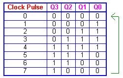
Again, the apparent disadvantage of this counter is that the maximum available states are not fully utilized. Only eight of the sixteen states are being used.
Beware that for both the Ring and the Johnson counter must initially be forced into a valid state in the count sequence because they operate on a subset of the available number of states. Otherwise, the ideal sequence will not be followed.
BLOCK DIAGRAM
TRUTH TABLE
RING COUNTERS:
A ring counter is basically a circulating shift register in which the output of the most significant stage is fed back to the input of the least significant stage. The following is a 4-bit ring counter constructed from D flip-flops. The output of each stage is shifted into the next stage on the positive edge of a clock pulse. If the CLEAR signal is high, all the flip-flops except the first one FF0 are reset to 0. FF0 is preset to 1 instead.
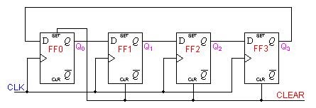
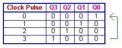
Since the count sequence has 4 distinct states, the counter can be considered as a mod-4 counter. Only 4 of the maximum 16 states are used, making ring counters very inefficient in terms of state usage. But the major advantage of a ring counter over a binary counter is that it is self-decoding. No extra decoding circuit is needed to determine what state the counter is in.
Verilog Code:
/*code is generated for Johnson counter only*/

module johnson_counter(
 Clock,
 Reset,
 Count_out
);

input Clock;
input Reset;
output [3:0] Count_out;
reg [3:0] Count_temp;

always @(posedge(Clock) or Reset)
begin

 if(Reset == 1'b1)
 begin

  Count_temp <= 4'b0000;

 end
 else if(Clock == 1'b1)
 begin

  Count_temp <= {Count_temp[2:0],~Count_temp[3]};

 end

end

assign Count_out = Count_temp;

endmodule
TEST BENCH:
module j_tb_v;

    // Inputs
    reg Clock;
    reg Reset;

    // Outputs
    wire [3:0] Count_out;

    // Instantiate the Unit Under Test (UUT)
    johnson_counter uut (
        .Clock(Clock),
        .Reset(Reset),
        .Count_out(Count_out)
    );

    initial begin

        // Initialize Inputs
        Clock = 0;
        Reset = 1;
        #10 Reset = 0;

        // Wait 100 ns for global reset to finish
        #100;

        // Add stimulus here

    end

   always #5 Clock=~Clock;

endmodule
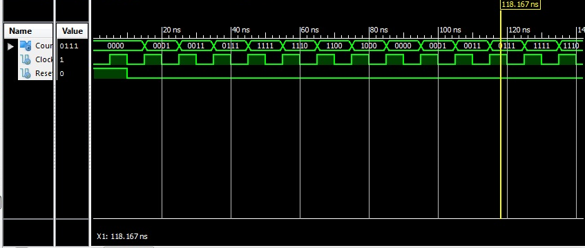
Result: Thus the program for Johnson ring counter has been verified and also simulation and synthesis reports have been verified.
Outcomes: After completion of this experiment students are able to design Johnson ring counter using Verilog code.
-
UpdatedOct 15, 2016
-
Views12,171