IC 565 - PLL Applications
Prerequisite: Basic operation of PLL and Pin diagram of IC 565.
Objective: To study the operation of NE565 PLL – with a given free running frequency.
Apparatuses:
- DC power supply
- CRO
- Bread Board
- Function Generator
- Resistors 2.2kΩ, 10KΩ, 18KΩ – 1No. each
- Capacitor 10µF – 1No
- Capacitor 0.001µF – 2Nos
- IC565 - 1No
Theory:
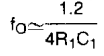
The 565 IC is available as a14-pin DIP package. The output frequency of the VCO is fo = 1.2 /4 RTCT, where RT and CT are the external Resistor and Capacitor connected to pin 8 and pin 9. A value between 2k and 20k is recommended for RT. The VCO free running frequency is adjusted with RT and CT, so that it is at the centre of the input frequency range.
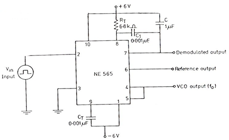
Circuit diagram:

Procedure:
- Connect the circuit as shown in the figure.
- Measure the free running frequency of VCO at pin 4 with the input signal Vin = zero. Compare it with the calculated value = 1.2/4RTCT
- Now apply the input signal of 1Vpp square wave of 100Hz to pin 2. Connect channel 1 of the CRO to pin 2 and display this signal on the scope.
- Gradually increase the input frequency till the PLL is locked to the input frequency.
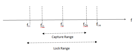
- This frequency fCL gives the lower end of the capture range.
- Go on increase the input frequency, till PLL stops tracking the input signal. This frequency fLH gives the upper end of the lock range.
- If the input frequency is increased further the loop will be in unlocked condition only.
- Now gradually decrease the input frequency till the PLL is again get locked. This is the frequency fCH, the upper end of the capture range. Keep on decreasing the input frequency until the loop is unlocked. This frequency fLL gives the lower end of the lock range.
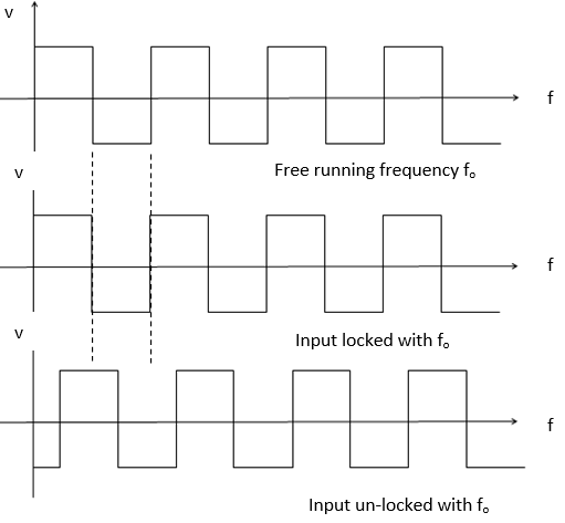
Expected Wave Forms:
Result:
fO Free running frequency:
fLL Lower Locking frequency:
fCL Lower capture frequency:
fCH Higher capture frequency:
fLH Higher Locking frequency:
Outcome: After conducting this experiment, students are able to understand the applications of PLL.
VIVA Questions:
1. What are the basic blocks of a PLL?
Ans: A phase detector, low pass filter, amplifier and a VCO in feedback loop.
2. Define VCO?
Ans: A voltage controlled oscillator is an oscillator circuit in which the frequency of oscillations is controlled by an externally applied voltage.
3. What is the formula for the free running frequency Fo of 565 PLL?
Ans:
4. What is PLL?
Ans: A PLL is a closed loop system designed to lock output frequency and phase to the frequency and phase of an input signal.
5. Define lock range?
Ans: When PLL is in lock, it can track frequency changes in the incoming signal. The range of frequencies over which the PLL can maintain lock with the incoming signal is called as lock range.
6. Define pull-in time?
Ans: The total time taken by the PLL to establish lock is called pull-in time.
7. Define capture range?
Ans: The range of frequencies over which the PLL can acquire lock with the input signal is called as capture range.
8. What is the function of the LPF in PLL?
Ans: Controls the capture range and lock range of PLL.
9. What are the applications of PLL?
Ans: Frequency multiplication / Division, Frequency translation, AM detection, FM Demodulation, FSK Demodulator etc.
10. Which is greater – lock in range or capture range?
Ans: Lock in Range.
-
UpdatedOct 22, 2016
-
Views27,790