Finite State Machine (Moore Machine)
Prerequisites:
Study the functionality of Moore machine.
Learning Objective:
To develop the source code for Moore machine by using VERILOG and obtain the simulation and synthesis.

Software and Hardware:
Xilinx ISE 9.2i and FPGA Spartan-3E.
Theory:
In the theory of computation, a Moore machine is a finite state machine where the outputs are determined by the current state alone (and do not depend directly on the input). The state diagram for a Moore machine will include an output signal for each state, Compared with a Mealy machine, which maps transitions in the machine to outputs.
- The advantage of the Moore model is a simplification of the behavior

| Present State | Next State | Output | ||
|---|---|---|---|---|
| X = 0 | X = 1 | X = 0 | X = 1 | |
| S0 | S1 | S0 | 0 | 0 |
| S1 | S1 | S2 | 0 | 1 |
| S2 | S1 | S0 | 0 | 0 |
Block Diagram:

Verilog Code:
module FSM_Moore(y, x, clock, reset);
    input  x, clock, reset;
    output y;

    reg y;
     reg [1:0] Next_state;

    parameter s0 = 2'b00, s1 = 2'b01, s2 = 2'b10;

    always @ (posedge clock)
    begin
        if (reset)
        begin
            Next_state  =  s0;
            y = 1'b0;
        end

    case (Next_state)
            s0:begin
                    y = 1'b0;
                    if (x)
                        Next_state = s0;
                    else
                        Next_state = s1;
                end
            s1:begin
                    y = 1'b0;
                    if (x)
                        Next_state = s2;
                    else
                        Next_state = s1;
                end
            s2:begin
                    y = 1'b1;
                    if (x)
                        Next_state = s0;
                    else
                        Next_state = s1;
                end
        endcase
    end
endmodule
TEST BENCH:
module FSM_Moore_tb_v;

    // Inputs
    reg x;
    reg clock;
    reg reset;

    // Outputs
    wire y;

    // Instantiate the Unit Under Test (UUT)
    FSM_Moore uut (
        .y(y),
        .x(x),
        .clock(clock),
        .reset(reset)
    );

    initial begin

        // Initialize Inputs
        x = 0; clock = 0;reset = 1;
        #10 x = 0; reset = 0;
        #10 x = 1;
        #10 x = 0;
        #10 x = 1;
        #10 x = 0;
        #10 x = 1;

        // Wait 100 ns for global reset to finish
        #100;

        // Add stimulus here

    end

        always #5 clock = ~clock;

endmodule
Simulation Results:
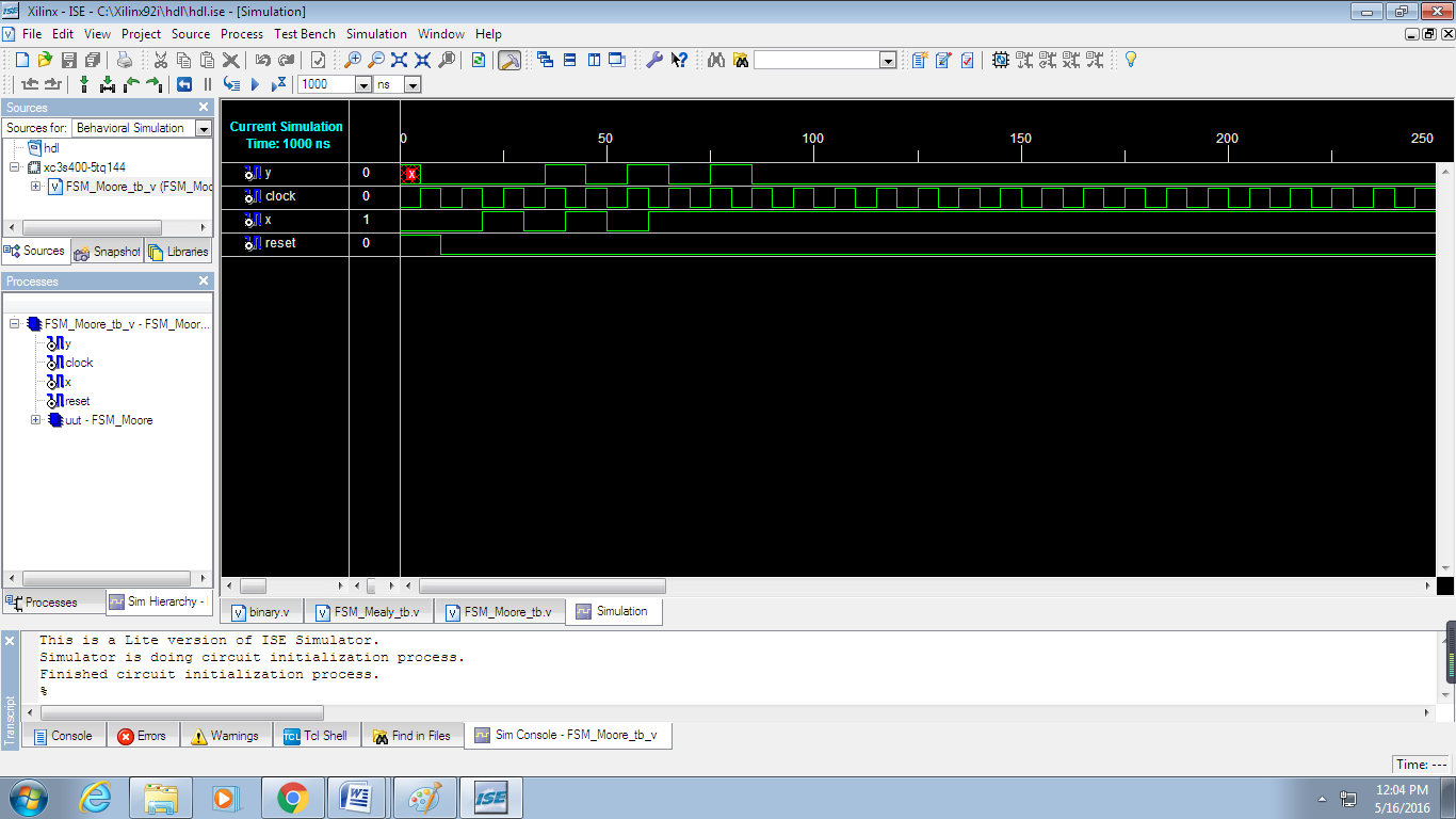
Result: Thus the program for Moore FSM has been verified and also simulation and synthesis reports have been verified.
Learning outcome:
After completion of this experiment, students are able to design moore machine using Verilog code.
Viva Questions:
- What is the function of Moore machine?
- What are the differences between Moore and Mealy machine?
- What is meant by simulation?
- What is meant by synthesis?
- What are advantages of verilog over high level languages?
-
UpdatedOct 17, 2016
-
Views4,249