Active filter applications - LPF, HPF
Prerequisite: Passive filters – operation, Low pass and high pass circuits characteristics (PDC).
Objective: To design first order low pass and high pass filters using op-amp 741 IC for a given cutoff frequency.
Apparatus:
| Bread board | 1 |
| Regulated power supply (0-30V) | 1 |
| CRO (20MHz) | 1 |
| IC 741 | 1 |
| Resistors | |
| R3 | 1 ( as per the design) |
5.86K |
1 |
| 10K |
1 |
| Capacitors | 1 |
| C3 | 1 ( as per the design) |
| Function Generator (10 Hz - 2MHz) | 1 |
| Connecting wires |
Design:
For a given cutoff frequency f = 1.59 KHz for a Low pass filter,
f = 1/(2πRC)
Assume C as 0.001μF
R = ? (Calculated as 100K)
For a given cutoff frequency f = 10 KHz for a High pass filter,
f = 1/(2πRC)
Assume C as 0.01μF
R = ? (Calculated as 1.5K)
Circuit diagrams:
LOWPASS FILTER
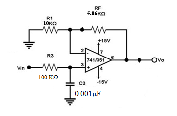
Fig 1. Active Low Pass Filter (1st order)
HIGH PASS FILTER
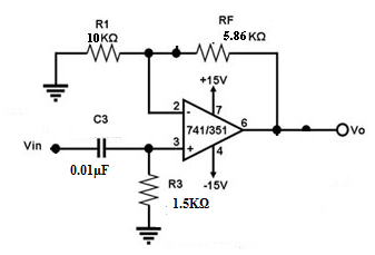
Fig 2. Active High pass Filter (1st order)
Procedure:
LOW PASS FILTER:
- Connect the circuit as shown in the low pass filter circuit diagram (fig.1).
- Apply 2Vp-p sine wave input to the resistor R2 at Vin.
- Keep the input voltage constant and vary the frequency on semi-log scale ranging from 10Hz to 1MHz and note down the corresponding outputs on CRO.
- 4.Observe the theoretical and practical values of the cutoff frequency.
- Draw the graph between voltage gain and frequency and mark the cutoff frequency.
TABULAR FORM:
Vin = 2Vp-p Sinusoidal Wave
| S.No | Input frequency (Hz) | Output Amplitude Vo (Vp-p) | Gain A = Vo/Vin | Gain in dB = 20log(A) |
|---|---|---|---|---|
| 1 | ||||
| 2 | ||||
| 3 | ||||
| 4 | ||||
| 5 | ||||
| 6 | ||||
| 7 | ||||
| 8 | ||||
| 9 | ||||
| 10 |
HIGH PASS FILTER:
- Connect the circuit as shown in the high pass filter circuit diagram (fig 2).
- Apply 2Vp-p sine wave input to the capacitor C2 at Vin.
- Keep the input as voltage constant and vary the frequency on semi-log scale ranging from 10Hz to 1MHz and note down the corresponding outputs on CRO. Observe the theoretical and practical voltage gains.
- Draw the graph between voltage gain and frequency and mark the cutoff frequency
TABULAR FORM:
Vin = 2Vp-p
| S.No | Input frequency (Hz) | Output Amplitude Vo (Vp-p) | Gain A = Vo/Vin | Gain in dB = 20log(A) |
|---|---|---|---|---|
| 1 | ||||
| 2 | ||||
| 3 | ||||
| 4 | ||||
| 5 | ||||
| 6 | ||||
| 7 | ||||
| 8 | ||||
| 9 | ||||
| 10 |
FREQUENCY RESPONSE PLOTS:
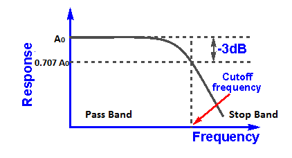
LOW PASS FILTER
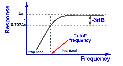
HIGHPASS FILTER
Result:
Designed and observed the first order and second order high pass and low pass filters for the given specifications.
Outcome:
After conducting these experiment students are able to design the Active low pass and high pass filters.
VIVA Questions:
1. Give the formula for cutoff frequency for the low pass filter?
Ans: Fh = 1/ 2π RC.
2. What is the difference between analog filter and digital filter?
Ans: Analog filter has less performance whereas digital filters have better performance. Digital filters are used in DIP applications.
3. To obtain a band reject filter, LPF and HPF are to be connected in ___________ method.
Ans: In Series with low value of cut off frequency for LPF and high value of cut off frequency for HPF.
4. To obtain a band pass filter, LPF and HPF are to be connected in ___________ method.
Ans: In Series with high value of cut off frequency for LPF and low value of cut off frequency for HPF.
5. What is bandwidth?
Ans: The frequency band between the low cut off and high cut off.
6. Define cut off frequency?
Ans: point which is 3dB less than the max gain ( 0.707 of max gain)
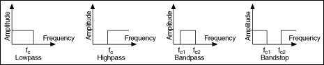
7. Draw the frequency response plot for an ideal filters.
Ans:
8. What are an active filter and a passive filter?
Ans: Active filter uses active components like Op-Amps. Passive filter uses passive components like R, L and C.
9. What is a filter?
Ans: An electronic circuit which passes the signal of frequencies which are required and rejects the signal of frequencies which are not required.
10. What is the rate of fall of the gain in stop band for first order and second order filter.
Ans: 20dB/decade or 6dB/octave for 1st order filter, 40dB/decade or 12dB/octave for 2nd order filter.
-
UpdatedOct 15, 2016
-
Views13,378