Monostable MultiVibrator
Pre-Lab:
1. Study the operation and working principle Monostable Multivibrator.
2. Study the procedure for conducting the experiment in the lab.
Objectives:
1. To study the operation and observe the wave forms of Monostable Multivibrator.
2. To Design a Monostable multivibrator for the pulse width of 0.3mSec.
Apparatus:
1. CRO 0 to 20 MHz (Dual channel) - 1No.
2. Function generator 1Hz to 1 MHz - 1No.
3. Capacitors (0.033µF) - 2 No.
4. Capacitor(0.01 µF)) - 1 No.
5. Resistors (1 k%u2126, 10k%u2126, 100K%u2126, 47K%u2126) - 2, 2, 1 and 1 Nos .
6. Transistor (BC 107) - 2 No.
7. Diode(IN4148) - 1 No.
8. Regulated Power supply 0 – 30 V(dual ) - 1 No.
9. Connecting wires
10. Bread board
Circuit diagram:

Theory:
The monostable circuit has one permanently stable and one quasi-stable state. In the monostable configuration, a triggering signal is required to induce a transition from the stable state to the quasi- stable state. The circuit remains in its quasi-stable for a time equal to RC time constant of the circuit. It returns from the quasi-stable state to its stable state without any external triggering pulse. It is also called as one-shot, a single cycle, a single step circuit or a univibrator.
Operation:
Assume initially transistor Q2 is in saturation as it gets base bias from VCC through R. coupling from Q2 collector to Q1 base ensures that Q1 is in cutoff. If an appropriate negative trigger pulse applied at collector of Q1 (VC1) induces a transition in Q2, then Q2 goes to cutoff. The output at Q2 goes high. This high output when coupled to Q1 base, turns it ON. The Q1 collector voltage falls by IC1 RC1 and Q2 base voltage falls by the same amount, as voltage across a capacitor ‘C’ cannot change instantaneously.
The moment, a negative trigger is applied at VC1, Q2 goes to cutoff and Q1 starts conducting. There is a path for capacitor C to charge from VCC through R and the conducting transistor Q1. The polarity should be such that Q2 base potential rises. The moment, it exceeds Q2 base cut-in voltage, it turns ON Q2 which due to coupling through R1 from collector of Q2 to base of Q1, turns Q1 OFF. Now we are back to the original state i.e. Q2 is ON and Q1 is OFF. Whenever trigger the circuit into the other state, it cannot stay there permanently and it returns back after a time period decided by R and C.
Pulse width is given as T = 0.69RCsec.F
Design Procedure:
To design a monostable multivibrator for the Pulse width of 0.3 mSec.
Let ICmax = 15mA, VCC = 15V, VBB = 15V, R1 = 10K%u2126.
T =0.69RC
Choose C = 10nf(0.01µF) T = 0.69 RC
0.3 x 10⁻³Sec = 0.69 x R x 10 x 10-9
R = 43.47 Kohms ≈ 47Kohms
RC = (VCC- VCESAT) / ICMAX = (15 − 0.3) / 15 X 10-3
= 1 Kohms
Minimum requirement of | VB1| ≤ 0.1
For more margin, given VB1 = -1.185
VB1 =  +
+ 
Substitute the values , R1=10kohms we will get R2= 100Kohms
Procedure:
1. Make the connections as per the circuit diagram.
2. Select the triggering pulse such that the frequency is less than 1/T
3. Apply the triggering input to the circuit and to the CRO’s channel and Connect the CRO channel-2 to
the collector and base of the Transistor Q1&Q2.
4. Adjust the triggering pulse frequency to get stable pulse on the CRO and now measure the pulse width
and verify with the theoretical value.
5. Obtain waveforms at different points like VB1, VB2, VC1 & VC2 and plot the graph.
Expected Waveforms:
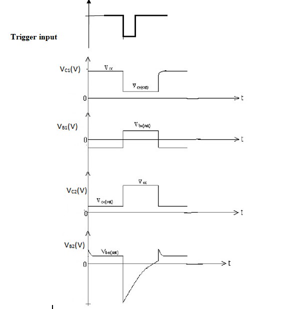
Theoretical calculations: TON = 0.69 RC
R= 47K%u2126 and C = 10nF or 0.01µF
Note: Normally Monostable Multivibrator generates single pulse output whenever a trigger is given. To observe this output storage oscilloscope is required.
Result: Monostable Multivibrator is designed; the waveforms are observed and verified the results theoretically.
Viva Questions:
- What is a multivibrator?
Ans: a multivibrator is a circuit which can operate at a number of frequencies .
- What are applications of Monostable Multivibrator?
Ans: it is used as gating circuit and as a delay circuit.
- The monostable multivibrator is also called __, ___, __, ___ or ___.
Ans: one shot, a single step circuit, un multivibrator , gating circuit and delay circuit .
- A Monostable Multivibrator generates __ wave
Ans; pulse waveform
- Why is the time period T also called Delay time?
Ans: in Quasi-stable state Q1 is ON and Q2 is OFF. The interval during which quasi- stable state of the multi persists i,e Q2 is dependent upon the rate at which the capacitor C discharges. This duration of Quasi-stable state is termed as delay time.
- Justify, Why Monostable Multivibrator is called one-shot circuit?
Ans: Because it produces only one pulse.
- What is a quasi state?
Ans; A quasi-stable state means a temporarily stable state . the circuit remains in the quasi-stable State only for a specified time and afterwards it comes back to other state .
- In monostable multivibrator, the coupling elements are __.
Ans: resistor and capacitor
- What is the formula for the pulse width of a Monostable multivibrator? To get a pulse width of 2 mSec., get the values of R and C.
Ans: T=0.69RC R=8K and C=200 µF
- ___ triggering is used in monostable multivibrator.
Ans; unsymmetrical triggering
Design Projects
1. Design a collector coupled monostable multivibrator using 2-BC107 transistor with 5ms quasi stable state duration VCC=10V , hfe(min)=30 IC(sat)=5mA.
2. Verify the output of monostable multivibrator by using different triggering methods.
Outcomes: After finishing this experiment students are able to design Monostable Multivibrator and able to explain its operation.
-
UpdatedSep 29, 2019
-
Views15,824